
Selecting an IDC connector sounds simple – match the pitch, count the pins, and place the order. But ask any design engineer who has faced a production delay because of a connector issue, and they’ll tell you the same thing: IDC connector selection is never “just a small decision.”
A ribbon cable that doesn’t fit. A connector blocked by a nearby capacitor. An enclosure that won’t close because the cable routing was overlooked. Or worse, intermittent signal failures that appear months later because strain relief was ignored.
These are not rare problems – they are common design mistakes that begin early in the PCB planning stage.
This is why choosing the right IDC connector is not just a procurement task; it is a reliability decision. The right connector improves assembly speed, serviceability, and long-term product performance. The wrong one can lead to expensive PCB respins, field failures, and unnecessary downtime.
In this guide, we’ll break down how to make the right IDC connector selection, from pitch and pin count to header type, mounting orientation, contact plating, and strain relief – so your design works smoothly from prototype to production.
IDC connector selection for Your PCB Design
Start with Pitch First
The first and most important step in IDC connector selection is deciding the pitch. Pitch refers to the centre-to-centre distance between adjacent pins, and once it is selected, everything else in the connector system must match. This includes the ribbon cable, the IDC female socket, and the PCB-mounted header.
If even one of these components is mismatched, the connector either will not mate at all or may create unreliable contact that causes long-term problems. This is why pitch should always be fixed early in the design process.
The three most common pitch sizes are 2.54mm, 2.00mm, and 1.27mm.
The 2.54mm pitch is the most widely used and is ideal for industrial control panels, consumer electronics, embedded systems, and general-purpose PCB designs. It is the easiest to source because it is commonly stocked across India, making it a practical choice for OEMs that need quick procurement and easy field servicing.
The 2.00mm pitch is a strong middle-ground option. It is commonly used in ARM and AVR programming headers, JTAG interfaces, and compact industrial boards. It saves PCB space without becoming too delicate for assembly and maintenance.
The 1.27mm pitch is used when board space becomes critical and high connector density is required. It is common in Raspberry Pi GPIO headers, compact controllers, and advanced debugging interfaces. At this level, precision becomes much more important, which is why sourcing reliable FRC connector PCB India solutions becomes critical for long-term consistency and performance.
Plan Pin Count with Future Margin
One of the most common mistakes engineers make during IDC connector selection is choosing the exact number of pins required for the current design. While this may seem efficient, it often creates expensive problems during the next product revision.
A new sensor may need to be added, extra grounding may become necessary, or additional debugging lines may be required. If the connector was selected with no spare capacity, the only solution becomes changing the connector and redesigning the PCB.
A much smarter approach is to keep a 10–20% margin in pin count from the beginning. For example, if the design currently requires 16 connections, selecting a 20-pin connector often makes far more sense than choosing a 16-pin option.
Most standard dual-row IDC connectors come in even pin counts such as 6, 8, 10, 14, 16, 20, 26, 34, 40, and 50. Odd pin counts generally increase complexity and cost, so planning with standard sizes is always the better decision.
Choosing the Right box header PCB
The PCB-mounted male connector is called the header, and selecting the right box header PCB has a direct impact on assembly ergonomics, reliability, and serviceability.
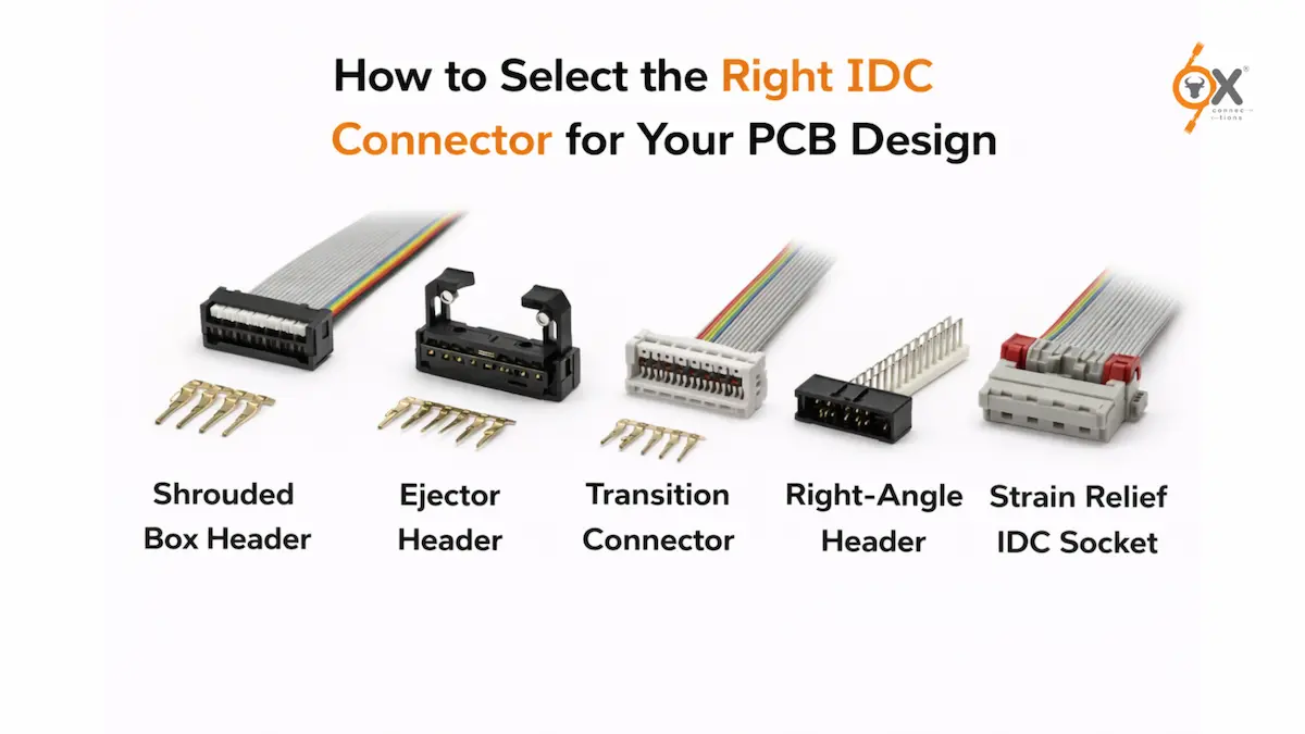
The standard shrouded box header is the most commonly used type and should be the default choice for most applications. It includes guided insertion, pin protection, and a polarisation notch that prevents reverse insertion. This reduces assembly mistakes and improves long-term reliability, especially in production environments where repeated connections are common.
An ejector header adds lever arms that help release the mating connector without pulling directly on the cable. This is especially useful when the connector is placed in a tight area or when frequent plugging and unplugging happens during production testing. It improves usability and reduces the risk of connector wear.
A transition connector, also called a board-in connector, allows the ribbon cable to terminate directly into the PCB-mounted connector without using a separate IDC socket. This works well for permanent internal wiring in sealed systems where the connection will not need regular servicing.
SMD box headers are chosen when the PCB follows a full SMT assembly process. They reduce through-hole requirements and support automated reflow soldering. However, because they offer lower mechanical strength, proper strain relief becomes even more important.
Straight or Right-Angle? Let Cable Routing Decide
Many engineers choose connector orientation based on habit rather than actual routing requirements. This often creates unnecessary mechanical issues later.
Straight headers allow the ribbon cable to exit vertically upward from the PCB. They work best in taller enclosures where there is enough vertical clearance and the cable can route upward before bending.
Right-angle headers allow the ribbon cable to exit parallel to the PCB surface. They are ideal for low-profile enclosures, compact industrial systems, and edge-mounted connectors where horizontal cable routing is necessary. They also reduce pull stress on solder joints because the cable does not create upward force on the header.
One commonly missed issue is physical clearance. Even if the connector fits perfectly on the PCB layout, nearby capacitors, standoffs, or enclosure walls may block the mating connector from seating properly. This problem is often only discovered during physical assembly, which is why mechanical clearance should always be checked early.
Contact Plating: Tin vs Gold
Most standard IDC connectors use tin-over-nickel contact plating, and for general industrial use, this is usually the correct choice. Tin plating offers good solderability, reliable contact resistance, and cost-effective production for standard applications.
However, some environments demand higher reliability.
Gold-plated contacts are better suited for medical equipment, telecom systems, industrial automation, and high-humidity environments where stable contact resistance must be maintained over time. Gold resists oxidation much better than tin, which helps prevent long-term signal issues.
The cost increase is relatively small compared to the cost of field failures, which is why many OEMs choose gold-plated options for critical systems where downtime is expensive.
Never Ignore Strain Relief
Strain relief is one of the most overlooked parts of connector design, yet it has a major impact on long-term reliability.
Without strain relief, every pull on the cable transfers force directly to the IDC contact points. Over time, this leads to loose connections, higher resistance, signal instability, and eventually field failures.
IDC sockets with built-in strain relief clamp the cable body so that the connector contacts remain protected. This is especially important in industrial machinery, control panels, vibration-heavy environments, and systems that require frequent servicing.
At smaller pitches like 1.27mm, where integrated strain relief is less common, additional cable management such as cable ties or adhesive supports should be included as part of the design documentation.
Skipping strain relief may save a small cost during assembly, but it often creates much bigger maintenance problems later.
Final Checklist Before Specification
Before finalising your connector design, engineers should always confirm a few basic points. The pitch must match across the cable, socket, and header. The pin count should include room for future expansion. The header type should match service and maintenance requirements. The orientation should support enclosure routing, and enough physical clearance must exist for the connector to mate fully.
It is also important to ensure that contact plating suits the operating environment, strain relief is included where needed, and the ribbon cable conductor count matches the connector specification.
These simple checks prevent expensive redesigns and production delays later.
Why OEMs Choose OX Connections
For Indian manufacturers, connector selection is not only about technical specifications. It is also about lead time, MOQ flexibility, stock availability, and reliable dispatch.
Many global suppliers come with long waiting periods and high order quantities, which slow down production schedules and create procurement challenges.
OX Connections solves that by offering complete FRC connector PCB India solutions across 1.27mm, 2.00mm, and 2.54mm pitch systems. We supply female sockets, straight headers, right-angle headers, ejector headers, and transition connectors with ready stock availability across India.
With over 5,000 products in stock and fast dispatch support, OXConnections helps OEMs move faster from design to production without unnecessary delays. Our connectors are trusted across industrial automation, renewable energy, medical equipment, and consumer electronics because reliability matters at every stage.
Because in PCB design, the right connector is never a small decision – and the right supplier makes all the difference.