
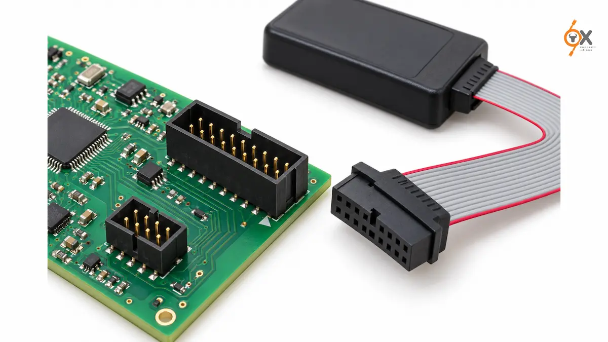
Learn how to choose a JTAG connector for PCB debugging. Compare 10-, 14- and 20-pin IDC headers, pitch, keying and ribbon cable options in India.
A colleague once spent an entire afternoon convinced his debugger firmware was corrupted. Board wouldn’t enumerate, no target detected, nothing. Turned out the JTAG connector on the new board revision had been laid out with pin 1 on the wrong corner. The chip was fine. The debugger was fine. The header just wasn’t where fifteen years of muscle memory expected it to be.
That’s the thing about JTAG hardware: the protocol itself is well documented and genuinely boring once you understand it, but the physical connector is where most of the real-world pain shows up. Wrong pitch, wrong pin count, a header that doesn’t survive more than a dozen insertions on the test bench. This is a working guide to the connector side of JTAG, written for engineers, PCB designers, and procurement teams who need to spec the right part rather than relearn the boundary-scan spec from scratch.
What JTAG Is Actually For
JTAG, formally IEEE 1149.1, was designed for boundary-scan testing: checking that every pin on a densely packed board is actually soldered where it should be, without physically probing each one. That’s still its job on a production line. But somewhere along the way, chip vendors realised the same serial interface could load firmware onto flash memory and step through code line by line on a live processor, and JTAG quietly became the default way to program and debug embedded hardware.
So on any given day, a JTAG header on a board might be doing one of three jobs: flashing firmware during manufacturing, giving a debugger real-time access to registers and memory during development, or running a boundary-scan test to catch a cold solder joint before the board ships. Same four or five signal lines, three completely different use cases.
Why IDC Box Headers Became the Default
Insulation-displacement connectors won this particular fight for a practical reason: you don’t need to strip or solder individual wires. A ribbon cable gets pressed onto the header in one motion, the contacts cut through the insulation, and you have a working connection in seconds. For a signal that’s used briefly during development or testing and then often left unpopulated in the final product, that’s exactly the trade-off you want, low cost, fast assembly, and a connector that doesn’t need a trained hand to terminate.
The box header, a shrouded, keyed version of the basic pin header, adds one more useful thing: it makes it physically hard to plug the ribbon in backwards. On a signal where reversed polarity can, in the worst case, put voltage where a ground pin should be, that’s not a small detail.
Pitch Selection: 2.54mm Isn’t the Only Option Anymore
2.54mm, the classic 0.1-inch spacing, is still what most engineers picture when they hear “JTAG header.” It’s easy to hand-solder, easy to probe with a standard test clip, and every debug pod on the market supports it. On a board with room to spare, there’s rarely a reason to pick anything else.
Space-constrained designs, wearables, compact IoT modules, anything where every square millimetre is negotiated, push toward finer pitches. A finer-pitch header shrinks the footprint considerably, but it also narrows your options: not every programmer or adapter pod supports every pitch out of the box, and a mismatch here means an adapter cable, or worse, a redesign. Check what your debug tool actually supports before locking the pitch into the PCB layout.
Commonly Used JTAG Pin Configurations
This is the part where a lot of guides hand you a single “standard” pinout and call it done. Don’t trust one that does. JTAG pin counts and pin assignments vary by chip vendor, by debug tool manufacturer, and sometimes by board revision within the same product line. 10-pin, 14-pin, and 20-pin headers are all in wide use, and the same pin count can carry different signal assignments depending on whose debugger you’re plugging in.
What stays fairly constant across most implementations is the presence of TCK, TMS, TDI, TDO, and a ground reference, sometimes alongside reset and power-sense lines. Where exactly those land on the header is not something to assume. Pull up your target chip’s datasheet and your debug probe’s connector spec before finalising the layout, every time, even if it’s a chip family you’ve used before.
This guide deliberately doesn’t publish a single pinout table for that reason: presenting one as “the” JTAG pinout would be actively misleading. Verify against your chip and programmer documentation before committing to a layout.
Matching the Connector to the Use Case
The right JTAG header changes depending on where in the product lifecycle it’s being used. A quick reference:
| Use Case | Suggested Connector | Why It Fits |
| Bench-level debugging during firmware development | Box header, straight, with an FRC female socket on the ribbon | Cheap, easy to swap, no tooling needed beyond a crimp press for the socket end |
| Production test fixture, connector mated and unmated repeatedly | Box header with an ejector or latch | The latch stops the ribbon walking off the pins after a few hundred insertions |
| Header mounted where board space is genuinely tight | Finer-pitch box header (2.00mm or below) instead of the standard 2.54mm | Smaller footprint, but confirm your programmer’s pod or adapter actually supports that pitch |
| Right-angle mounting because the enclosure lid sits close to the board | Box header, right-angle | Keeps the connector profile low without redesigning the enclosure |
| Permanent board-to-board link once debugging is done | Transition connector | Removes the header entirely from the production BOM once it’s no longer needed |
Ribbon Cables: The Part That Gets Overlooked
Teams spend real time picking the right header and then grab whatever ribbon cable is sitting in the drawer. Pitch matters here too, and a cable that doesn’t match the header pitch either won’t seat properly or will seat with the contacts misaligned, which is a worse failure mode because it often half-works. Confirm the ribbon’s pitch and conductor count against the header before ordering in bulk, not after the first batch arrives.
Common Mistakes Worth Avoiding
Assuming a pinout without checking: the single biggest source of “my debugger won’t connect” tickets on any embedded team.
Skipping the keying/shroud: an unshrouded pin header on a JTAG signal is an invitation for a reversed ribbon connector, and JTAG signals aren’t always forgiving of that.
Under-speccing for a test fixture: a header rated for occasional use won’t hold up to thousands of insertions on an automated test line; pick a latched or ejector variant there.
Sourcing JTAG and IDC Connectors
Ox Connections stocks box headers, FRC female connectors with strain relief, ejector headers, and transition connectors across 1.25mm, 2.00mm, and 2.54mm pitch, in 6-pin to 64-pin configurations, straight and right-angle. Grey flat ribbon cable is available in matching pitches for the cable side of the connection. Over 5,000 products are in stock for quick dispatch across India, which matters when a header choice made in layout turns into a bulk order for a production run. Browse the full range on the IDC FRC Connectors & Flat Cables page.
Specifying JTAG headers for an upcoming board or need a bulk quote for a production run? Get in touch with Ox Connections for pricing, or request the product catalogue for the complete connector range.
Leave A Comment