
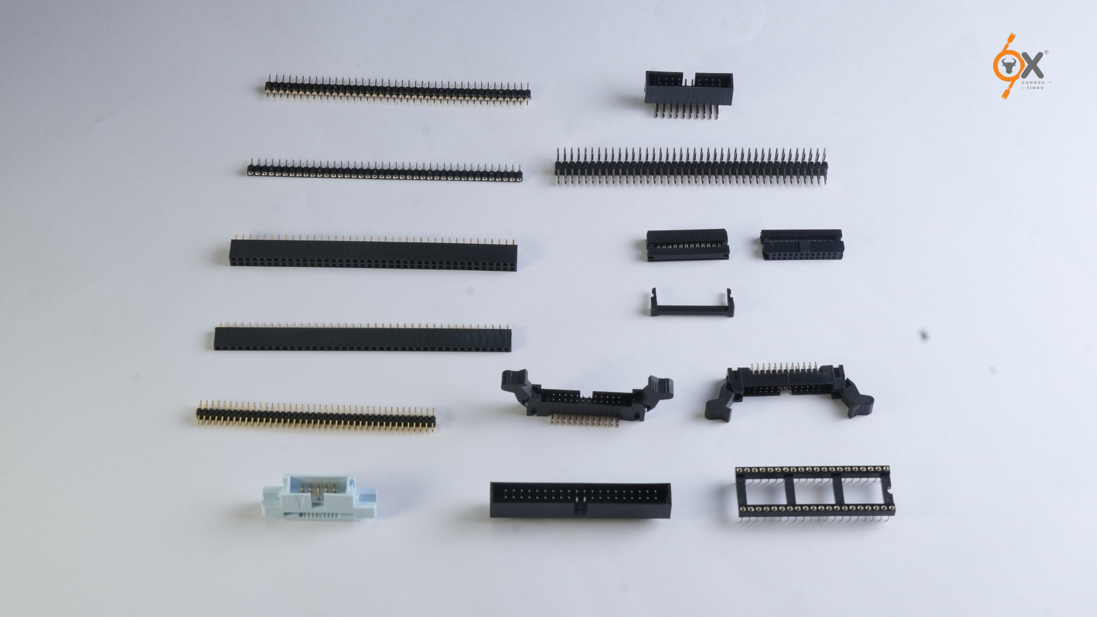
IDC (Insulation Displacement Contact) connectors eliminate the wire stripping and crimping steps that slow down electronics assembly. A flat ribbon cable is pressed into the connector housing, where sharp contacts pierce the insulation to create an electrical connection. No wire preparation is required, and no special tools are needed beyond a simple bench vise or press. Assembly that would take minutes with traditional crimping can be completed in seconds.
Combined with flat ribbon cables, IDC connectors allow multiple conductors to be terminated in a single plane. This creates organized, space-efficient wiring in applications ranging from consumer electronics to industrial control panels. In production environments assembling hundreds or thousands of units, the time savings and assembly consistency become significant.
Summary: IDC and FRC connectors enable fast, tool-less termination of flat ribbon cables for production electronics. Available in 1.27–2.54mm pitch and 6–64 pin counts, they reduce assembly time, improve consistency, and are widely used in consumer, industrial, and embedded systems.
What Is an IDC Connector?
An IDC (Insulation Displacement Contact) connector forms an electrical connection by cutting through the insulation of a wire and contacting the conductor directly. This eliminates the need for stripping or crimping, reducing assembly steps and improving consistency.
How IDC Connector Technology Works
IDC connectors contain V-shaped or fork-shaped contacts with sharp edges. When a ribbon cable is pressed into the connector, these contacts displace the insulation and make direct contact with the conductor inside. Spring tension in the contact creates a gas-tight connection that maintains electrical continuity without soldering or crimping.
The main advantage is assembly simplicity. No insulation stripping is required, and no dedicated crimp tools are needed. Multi-pin connectors can be assembled in seconds using a bench vise or press. The process is consistent across operators, reducing the risk of assembly errors in production.
FRC Connector Types
Female Connectors with Strain Relief
These connectors include integrated strain relief that grips the ribbon cable and reduces mechanical stress on the IDC contacts. They mate with male pin headers on PCBs and are recommended where cables may experience movement.
Box Headers (Straight and Right-Angle)
Shrouded male headers protect pins and provide polarization to prevent incorrect mating. Straight versions mount perpendicular to the PCB, while right-angle versions route cables parallel to the board surface.
Ejector Headers
Ejector headers include levers or tabs that assist with disconnecting cables in densely packed assemblies. They are useful where connectors are difficult to access by hand and are available in straight and right-angle versions.
Transition Connectors
These connectors allow transitions between different connector styles or between cable and PCB mounting, offering additional routing flexibility.
SMD Headers
Surface-mount headers attach directly to the PCB without through-holes, saving board space and supporting automated assembly processes.
Straight connectors are typically used when cables exit perpendicular to the board, while right-angle connectors reduce overall height and are better suited for parallel cable routing.
Flat Ribbon Cable Specifications
Pitch
Available in 1.27mm, 2.00mm, and 2.54mm. Smaller pitch enables higher wiring density, while larger pitch provides easier handling and higher current capacity. The pitch must match both the IDC connector and the PCB header.
Conductor Count
Typically ranges from 6 to 64 conductors. Higher pin counts allow multiple signals to be consolidated into a single cable assembly, reducing wiring clutter.
Construction
Most flat ribbon cables use 28 AWG conductors with PVC insulation in a grey, flat configuration. The flat geometry simplifies routing in confined spaces and maintains consistent conductor spacing.
Current Capacity
28 AWG conductors generally support 1–2A per conductor depending on ambient temperature and cable length. For power applications, current requirements and voltage drop should be verified against cable specifications.
Where IDC and FRC Connectors Are Commonly Used
Consumer Electronics
Used for internal connections in printers, scanners, displays, and audio equipment, where fast assembly and compact cable routing are important.
Industrial Control Panels
Suitable for I/O wiring, sensor interfaces, and actuator connections. Polarized connectors help prevent wiring errors during installation and maintenance.
Embedded Systems
Common on development boards and modules for expansion interfaces, debug connections, and peripheral links using standard header pitches.
Telecom Equipment
High pin-count ribbon cable assemblies help manage signal routing in rack-mounted systems where space is limited.
Test and Measurement Equipment
IDC connectors allow quick reconfiguration of test fixtures without specialized tools, making them practical for changing test setups.
Selection Guide for IDC and FRC Connectors
Pin Count: Include all signal, ground, and power connections. Allow margin for future expansion if required.
Pitch: Match the PCB header spacing (1.27mm, 2.00mm, or 2.54mm).
Mounting Style: Choose straight or right-angle based on cable routing and height constraints.
Header Type: Box headers for protection, ejector headers for easy removal, SMD headers for space-constrained designs.
Strain Relief: Recommended where cables experience movement or pull forces.
Cable Length: Measure routing paths accurately to avoid excess tension or clutter.
What OX Provides
OX Connections stocks IDC and FRC connectors in standard pitches (1.27mm, 2.00mm, and 2.54mm) and pin counts from 6 to 64 pins, sourced from Neltron and OX brands. Available connector types include female connectors with strain relief, box headers (straight and right-angle), ejector headers, transition connectors, and SMD headers. Grey flat ribbon cables are available in multiple conductor counts and pitches.
Standard configurations ship within days from existing stock. Custom cable lengths or specialized configurations typically require two to three weeks. All products are selected for consistent contact performance, reliable insulation displacement, and durable housings suitable for production assembly.
Frequently Asked Questions
What tools are needed for IDC connector assembly?
A bench vise or simple arbor press is sufficient for low-volume assembly. Production environments often use dedicated IDC presses or pneumatic tools for faster and more consistent results.
How do I prevent reversed ribbon cable connections?
Most IDC connectors include polarization features and pin-1 markings. Align the coloured stripe on the ribbon cable with the connector’s pin-1 indicator during assembly.
Can IDC connectors be reused?
IDC connectors are designed for one-time assembly. Reuse may be possible once, but repeated termination reduces contact reliability.
Are flat ribbon cables suitable for high-speed signals?
They are suitable for control signals, parallel buses, and moderate-speed interfaces. For high-speed differential signals, twisted-pair or shielded cables are recommended.
Next Steps
Contact om.advani@oxconnections.com with your requirements, including pin count, pitch, connector type (straight, right-angle, ejector, or SMD), and cable length if pre-assembled cables are required. Providing application details helps ensure correct component selection.
Technical specifications, drawings, and electrical ratings are available on request. Typical response time is 24–48 hours, with standard configurations shipping within days.