
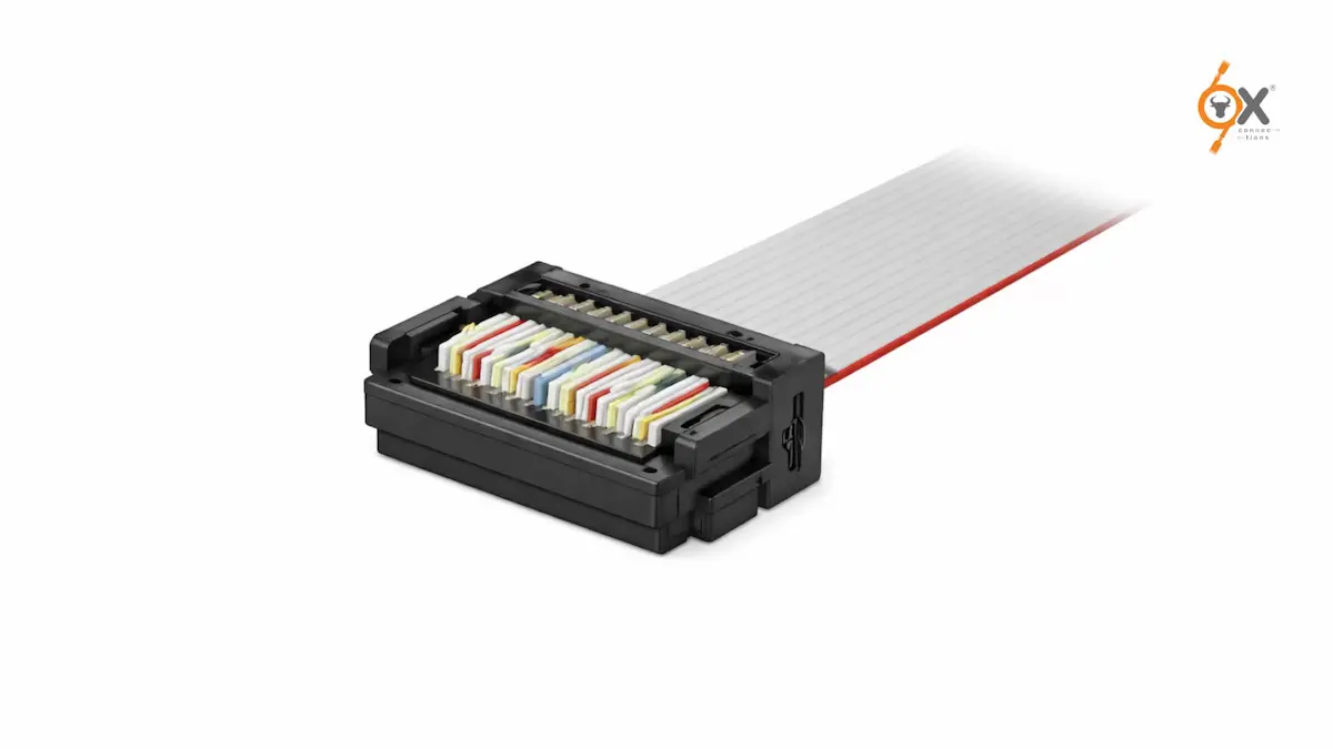
In electronics manufacturing – especially across busy production hubs like Mumbai, Pune, Ahmedabad, and Chennai – this happens more often than most teams would like to admit. A control panel works perfectly during testing, but once it reaches the customer site, intermittent faults begin. A ribbon cable looks properly installed, yet signals start dropping. In many cases, the issue is not the PCB or the machine itself – it comes down to poor IDC connector assembly.
For OEMs and production teams, this is a costly problem. One wrongly terminated cable can delay dispatch, trigger field complaints, and even damage customer trust. Most of these failures are caused by a few simple assembly mistakes that are completely preventable.
That’s exactly why getting IDC connector assembly right matters.
Whether you’re working with industrial automation panels in Andheri, medical equipment manufacturing in Navi Mumbai, or electronics assembly lines in Pune, proper FRC cable termination is critical for long-term reliability.
This guide covers the complete process – from choosing the right tools and understanding the correct IDC crimping process, to avoiding the most common ribbon cable assembly mistakes that lead to expensive field failures.
Because in production, the smallest connection often carries the biggest responsibility.
Why IDC Connectors Are Widely Used
IDC stands for Insulation Displacement Contact.
Unlike traditional crimping or soldering, IDC connectors do not require stripping insulation before termination. The connector contacts pierce through the insulation and make direct contact with the conductor inside.
This makes the process faster, cleaner, and highly efficient – especially for flat ribbon cables where multiple conductors need simultaneous termination.
That’s why IDC connector assembly is common in:
- PCB box header connections
- Industrial automation systems
- Telecom equipment
- Consumer appliances
- Medical electronics
- Automotive systems
- Embedded electronics
- Control panels
It saves time, improves consistency, and reduces manual labor – but only when done correctly.
Tools Required for IDC Connector Assembly
The right tool depends on production volume and connector pitch. Using the wrong one is one of the biggest causes of field failures.
Let’s look at the three most common options.
1. Bench Vise for Low-Volume Work
For prototypes, sample builds, and small production batches, a bench vise or machinist vise is often enough.
The process is simple:
- Position the cable correctly inside the connector
- Hand-close the cover lightly
- Place the connector evenly between vise jaws
- Tighten until the connector snaps fully shut
The key is even pressure.
Using pliers or tools that apply force at one point can crack the housing or create uneven contact seating. If the vise jaws are narrow, flat support blocks like hardwood or aluminium help distribute pressure evenly.
This method works well for basic IDC connector assembly in low-volume environments.
2. Dedicated IDC Hand Press
For regular production work, a dedicated IDC hand press is the better option.
These tools offer:
- controlled press force
- connector-specific die sets
- consistent seating
- reduced operator variation
- repeatable results
For 2.54mm pitch connectors, interchangeable dies are widely available. For 1.27mm and 2.00mm pitch connectors, the die must match the exact connector series.
Using the wrong die can damage both housing and contacts.
This is where the IDC crimping process becomes far more reliable.
3. Pneumatic or Semi-Automatic Press
For high-volume production, automation makes more sense.
Pneumatic and semi-automatic IDC machines provide:
- faster throughput
- highly consistent force
- lower labor cost
- process validation
- quality control support
For OEMs working under strict quality systems, this becomes essential.
Especially when connector failure can stop an entire machine in the field.
Step-by-Step IDC Connector Assembly Process
No matter what tool you use, the sequence remains the same.
Most failures happen because steps are skipped – not because the connector itself is faulty.
Let’s go step by step.
Step 1: Cut the Cable Square
Always cut the ribbon cable at a full 90-degree angle.
A diagonal or rough cut causes uneven conductor entry, leading to inconsistent contact penetration and unreliable performance later.
Use:
- sharp cable cutters
- straight-edge blade cutting
- dedicated ribbon cable tools
Clean cuts are the foundation of proper FRC cable termination.
Step 2: Identify Pin 1 Correctly
This is the most important step.
On standard grey ribbon cable:
The red stripe always indicates Pin 1.
On rainbow ribbon cable:
The brown conductor is usually Pin 1.
On the IDC connector housing, Pin 1 is marked using:
- a triangle
- arrow
- raised V mark
- molded symbol
Before placing the cable, confirm that the red stripe aligns with the Pin 1 marker.
This simple check prevents reverse polarity -the most damaging mistake in IDC connector assembly.
And once the connector is closed, this error is often impossible to detect visually.
Step 3: Position the Cable Properly
Open the connector housing and place the cable flat across the lower body.
Make sure:
- the cable edge sits flush
- the cable is straight
- there is no twist
- it sits naturally in guide grooves
Never force the cable.
If the cable enters at an angle, conductors may contact neighboring pins instead of the correct contacts.
Many serious ribbon cable assembly mistakes begin right here.
Step 4: Hand-Close the Cover
Press the upper cover down gently by hand.
This helps:
- hold the cable in place
- allow final visual checks
- confirm pin-1 alignment
- prevent movement during pressing
Before pressing, check again:
- red stripe alignment
- straight cable path
- no twist
- proper seating
This second check prevents expensive rework later.
Step 5: Press to Full Closure
Now place the connector inside the press tool and apply full force.
A properly terminated connector should have:
- full closure
- no visible gap
- flush fitting around the perimeter
If one side shows a gap, the press force was uneven.
Do not try to fix it by pressing again.
This often damages the contacts permanently.
Instead, reject the assembly and terminate again using a fresh cable section.
This is one of the most important rules in professional IDC crimping process.
Step 6: Attach Strain Relief
If the connector includes strain relief, install it now.
The cable folds back over the connector body, and the strain relief locks into place.
Its job is simple – it protects the contact points from movement stress.
It is functional, not decorative.
Skipping strain relief may save time during production but creates major reliability problems later.
Step 7: Final Verification
Before installation:
- perform a gentle pull test
- inspect full closure
- confirm no visible gaps
- check cable straightness
- verify both connector ends align correctly
If continuity testing is part of production, do it now.
Not later.
Common Mistakes That Cause Field Failures
Most failures happen because of process shortcuts.
Here are the biggest ones.
Reversed Pin 1 Orientation
This is the most common error.
Especially when the PCB header has no physical key, reverse insertion reaches the board without resistance.
The result may be:
- immediate board damage
- hidden signal faults
- delayed intermittent failures
The fix is simple:
Never skip Pin 1 verification.
Uneven Press Force
Using the wrong tool leaves some contacts incompletely seated.
It may pass testing initially – but fail later under vibration, heat, or shipping stress.
This creates difficult intermittent failures.
Correct tooling prevents this.
Angled Cable Entry
If the cable enters at an angle, conductors may touch neighboring pins.
This causes short circuits and cross-connections.
It often cannot be identified visually.
Only proper placement prevents it.
Skipping Strain Relief
Without strain relief, every cable movement stresses the IDC contacts directly.
Over time:
- contacts loosen
- resistance rises
- field failures increase
This is one of the most common ribbon cable assembly mistakes.
Wrong Cable Gauge or Pitch
Using the wrong cable size creates poor contact penetration.
Examples include:
- 00mm cable inside a 2.54mm connector
- incorrect AWG mismatch
Always verify:
- cable pitch
- conductor count
- AWG size
- datasheet compatibility
before assembly begins.
Why OEMs Choose OX Connections
Reliable assembly starts with reliable sourcing.
OX Connections supplies IDC and FRC connectors across:
- 27mm pitch
- 00mm pitch
- 54mm pitch
with pin counts from 6 to 64 pins, along with matching grey flat ribbon cables from 10 core to 64 core.
Unlike many global brands with long lead times and high MOQs, OX offers:
- ready stock availability
- fast dispatch across India
- cost-effective alternatives
- UL, RoHS, and CE-compliant products
- trusted quality for OEM applications
With over 5,000 products in stock, OX supports OEMs across solar, medical devices, home appliances, EV systems, renewable energy, and industrial electronics.
Because production delays should never begin with connectors.
Final Thoughts
Good IDC connector assembly is not complicated.
But it demands discipline.
Most failures come from small shortcuts – a skipped pin check, rushed pressing, missing strain relief, or the wrong cable size.
And those small shortcuts become expensive service calls later.
The goal is not just fast assembly.
It is reliable assembly.
Because in electronics manufacturing, the connector that “almost works” is usually the most expensive one of all.
FAQs
1. What is the most common mistake in IDC connector assembly ?
The most common mistake is incorrect Pin 1 orientation. If the red stripe on the ribbon cable does not align with the Pin 1 marking on the connector, it can cause reverse polarity, signal failure, or even PCB damage. This is why Pin 1 verification is the most critical step in IDC connector assembly.
2. Why is strain relief important in FRC cable termination ?
Strain relief protects the IDC contact points from movement and vibration. Without it, regular cable movement transfers stress directly to the contacts, which can cause loosening, higher resistance, and long-term field failures. Proper strain relief improves the reliability of FRC cable termination significantly.
3. Can I use a bench vise instead of a dedicated IDC press?
Yes, for prototypes and low-volume production, a bench vise can work well if pressure is applied evenly across the full connector width. However, for regular production and better consistency in the IDC crimping process, a dedicated IDC hand press or pneumatic press is strongly recommended.