
Learn how to select the right PCB Mount SMA Connectors for your RF design. Explore SMA Connector Footprint requirements, RF performance considerations, mounting styles, and sourcing best practices for OEM applications.
Why PCB Mount SMA Connectors Matter in Modern RF Design
Whether you’re designing wireless communication equipment, IoT devices, test instruments, industrial automation systems, or antenna modules, connector selection plays a crucial role in overall RF performance.
While significant engineering effort is often invested in antenna design, PCB layout, shielding, and component selection, the connector interface can sometimes be overlooked. Yet a poorly selected or improperly integrated connector can negatively impact signal integrity, introduce impedance discontinuities, and create reliability challenges during production.
This is where the PCB Mount SMA Connector becomes an important design element.
Widely used across RF and microwave applications, SMA connectors provide a compact, reliable, and mechanically secure interface between PCB circuitry and external RF systems. However, selecting the correct connector involves far more than simply matching mechanical dimensions.
Engineers must consider footprint design, mounting style, impedance control, assembly requirements, and long-term sourcing availability.
This guide explores the key considerations for selecting and integrating PCB Mount SMA Connectors in professional RF applications.
Understanding the PCB Mount SMA Connectors
A PCB Mount SMA Connector is designed to attach directly to a printed circuit board while providing an RF connection to external cables, antennas, or test equipment.
Unlike cable-mounted connectors, PCB-mounted versions become part of the board assembly itself and must integrate seamlessly with the PCB design.
These connectors are commonly used in:
- RF communication equipment
- Wireless modules
- Cellular devices
- GPS systems
- IoT gateways
- Test and measurement equipment
- Industrial wireless controls
- Antenna interface assemblies
Because the connector directly interfaces with the RF signal path, its design and placement can significantly influence overall system performance.
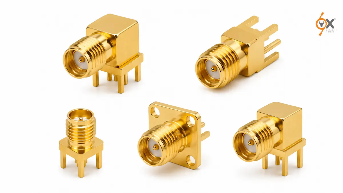
Choosing the Right Mounting Style
One of the first decisions engineers face is selecting the appropriate mounting configuration.
Several common styles exist:
Edge-Mount SMA Connectors
Edge-mount connectors are installed at the edge of the PCB and are often preferred for RF applications requiring controlled impedance transitions.
Benefits include:
- Compact integration
- Simplified cable connection
- Improved signal path continuity
- Efficient use of board space
Vertical PCB Mount Connectors
Vertical connectors are mounted perpendicular to the PCB surface and are commonly used where enclosure design requires upward-facing access.
Right-Angle PCB Mount Connectors
Right-angle configurations help accommodate mechanical constraints and can simplify cable routing within compact assemblies.
The optimal choice depends on board layout, enclosure design, antenna placement, and assembly requirements.
Why the SMA Connector Footprint Is Critical
One of the most overlooked aspects of RF connector integration is the SMA Connector Footprint.
The footprint serves as the physical and electrical interface between the connector and PCB.
An improperly designed footprint can lead to:
- Poor solder joint reliability
- Mechanical instability
- Impedance discontinuities
- Increased signal reflections
- Manufacturing inconsistencies
A well-designed SMA Connector Footprint should align with the connector manufacturer’s recommended dimensions and PCB stack-up requirements.
Engineers should avoid modifying footprint dimensions without thoroughly evaluating the potential impact on RF performance and manufacturability.
Impedance Matching and Signal Integrity
For RF engineers, maintaining controlled impedance throughout the signal path is a fundamental design objective.
Most RF systems are designed around a 50-ohm impedance environment. Any abrupt transition between PCB traces and the connector interface can introduce reflections and signal degradation.
When integrating a PCB Mount SMA Connector, designers should focus on:
Controlled Trace Geometry
PCB transmission lines should be designed to maintain consistent impedance from the RF circuitry to the connector interface.
Grounding Strategy
Proper grounding around the connector helps create a stable RF return path and minimizes unwanted electromagnetic effects.
Transition Optimization
The connector-to-PCB transition should be designed to reduce impedance discontinuities and preserve signal integrity.
PCB Stack-Up Considerations
Board thickness, dielectric properties, and copper geometry all influence impedance performance.
Even a high-quality connector may not deliver optimal results if the surrounding PCB design is not properly engineered.
RF Performance Considerations
An RF PCB Connector is expected to perform reliably across a range of operating frequencies.
While specific performance characteristics depend on the connector model and application requirements, several factors consistently influence results.
Return Loss
Good impedance matching helps minimize reflected signals and improve overall RF efficiency.
Insertion Loss
Reducing signal loss across the connector interface contributes to improved system performance.
Shielding Effectiveness
Connector design and grounding play important roles in reducing electromagnetic interference.
Mechanical Stability
RF performance can be affected if connectors loosen or experience mechanical stress during operation.
For applications involving vibration, movement, or repeated cable connections, mechanical durability becomes especially important.
PCB Layout Best Practices
Successful integration of a PCB Mount SMA Connector depends heavily on PCB layout quality.
Several best practices are commonly followed by RF design teams:
Keep RF Traces Short
Shorter RF paths generally help reduce losses and minimize opportunities for signal degradation.
Maintain Consistent Ground Reference
A continuous ground plane helps support controlled impedance and stable RF performance.
Avoid Unnecessary Discontinuities
Sudden changes in trace width or routing can negatively affect signal quality.
Follow Manufacturer Recommendations
Connector manufacturers typically provide footprint and layout guidance based on extensive testing.
Adhering to these recommendations helps improve both performance and manufacturability.
Manufacturing and Assembly Considerations
Beyond RF performance, practical manufacturing requirements should also influence connector selection.
Factors to evaluate include:
Assembly Process Compatibility
The connector should align with the production processes used by the contract manufacturer.
Mechanical Retention
Strong mechanical attachment improves long-term reliability.
Inspection Accessibility
Connectors should allow efficient quality inspection during production.
Repair and Replacement Requirements
Some applications may require field servicing or maintenance access.
Balancing RF performance with production practicality helps reduce overall lifecycle costs.
Sourcing Considerations for OEMs
For OEMs, connector selection extends beyond engineering requirements.
Procurement teams must also evaluate:
Supply Continuity
Consistent product availability is critical for maintaining production schedules.
Product Quality
Reliable connector quality helps reduce field failures and warranty risks.
Standardization
Using common connector platforms across multiple product lines can simplify inventory management.
Technical Support
Access to product information and application guidance can streamline engineering decisions.
Early collaboration between engineering and procurement teams often leads to more efficient sourcing outcomes.
Common Mistakes to Avoid
Several recurring mistakes can impact RF connector performance and procurement efficiency.
These include:
- Selecting a connector before finalizing PCB layout
- Ignoring SMA Connector Footprint recommendations
- Failing to verify mechanical compatibility
- Overlooking impedance transition design
- Choosing components based solely on initial cost
- Neglecting long-term supply considerations
Addressing these issues during the design phase helps prevent costly redesigns later.
Conclusion
Selecting the right PCB Mount SMA Connector involves much more than choosing a connector that fits the board.
Engineers must evaluate footprint design, mounting style, impedance control, signal integrity requirements, manufacturing considerations, and long-term sourcing strategy.
A carefully designed SMA Connector Footprint combined with sound RF layout practices can help ensure reliable performance throughout the product lifecycle. Likewise, selecting a dependable RF PCB Connector supplier supports production continuity and reduces procurement risk.
OX Connections: Supporting RF Design and OEM Production
OXConnections supplies a comprehensive range of SMA and RF connectivity solutions designed to support engineers, OEMs, and procurement teams across multiple industries.
As a stocking distributor, OX Connections offers access to a broad portfolio of SMA and RF connector solutions backed by competitive commercial terms, consistent top-notch quality, and a proven track record supporting OEM requirements. Whether supporting new product development or ongoing production programs, OX helps customers secure reliable connector supply from a trusted long-term sourcing partner.
For engineering teams seeking dependable RF connectivity solutions, OX Connections provides both product availability and sourcing confidence.
Disclaimer
Connector selection should always be validated against application requirements, PCB design parameters, operating frequency ranges, environmental conditions, and manufacturer specifications. Final product suitability remains the responsibility of the equipment designer and system integrator.
Leave A Comment