
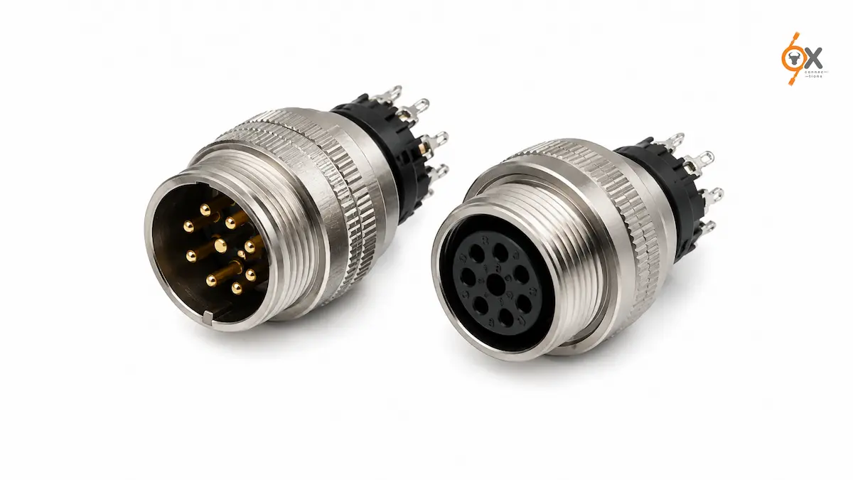
How a connector gets wired often decides how reliable it stays over years of service. Crimped and IDC terminations get most of the attention in industrial wiring discussions. But for many M-Series applications, the humble solder type connectors is still the preferred choice, and for good reason.
This guide walks through solder type male and female connectors, when to use each, and what to get right during assembly.
What a Solder Type Termination Actually Means
You terminate a solder type connector by soldering individual wires directly to the connector’s contacts, rather than using a crimp tool or insulation displacement method.
This is one of the oldest and most direct termination methods available. And it remains popular precisely because it creates a solid, low-resistance electrical joint without requiring specialised crimping equipment for every wire gauge.
Across the M-Series range, solder type versions are available in both male and female configurations. Giving flexibility depending on which side of the connection needs to be built into a cable assembly versus a fixed housing.
Male vs Female: Choosing the Right Side
The male connector carries the pins, while the female connector carries the sockets that receive them.
And the choice between the two usually comes down to which side of the connection is more exposed or vulnerable to damage.
As a general convention in industrial wiring, installers often place the female socket on the side more likely to carry live voltage when disconnected. Reducing the risk of accidental contact with an exposed pin.
Teams typically specify a solder type male female connector pair as part of a matched cable-to-housing assembly. So confirming both halves come from a compatible product line avoids fit or contact-alignment issues at final assembly.
Soldering Considerations for Reliable Joints
Getting a solder type termination right depends on a few basics: clean, properly stripped wire ends, adequate heat applied for a controlled duration, and enough solder to fully wet the joint without bridging adjacent contacts on closely spaced pins.
Overheating a contact during soldering can damage the connector’s internal insulation or plating. So following a controlled soldering process matters more on smaller M-Series sizes where pin spacing is tight.
Strain relief at the solder joint is equally important. Since a well-soldered but unsupported connection can still fail over time from repeated cable flexing near the termination point.
Using an appropriate boot, sleeve, or cable clamp alongside the solder joint helps the connection hold up under real-world handling.
Common Assembly Mistakes to Avoid
A frequent issue on solder type assemblies is applying too much solder. Which can wick up the wire strands beyond the joint and create a stiff point that’s more prone to fatigue cracking under vibration or repeated flexing.
Using just enough solder to fully wet the joint, without excess pooling around the contact, generally produces a more durable connection than a heavily soldered one.
Skipping a continuity check after assembly is another avoidable gap. Particularly on higher pin-count connectors where a cold joint or an accidental solder bridge between adjacent pins can be difficult to spot visually.
A quick continuity and isolation test before the connector goes into service catches most of these issues before they become a field failure.
Where Solder Type Connectors Fit Best
Solder type terminations are common in lower-volume production, prototyping, and applications where a custom cable assembly is being built in-house rather than sourced pre-terminated.
They also suit situations where a specific wire gauge or cable type falls outside standard crimp tooling ranges. Since soldering doesn’t depend on matching a crimp die to a wire size the way a crimp termination does.
Across the m series solder connector range, this makes solder type versions a practical option for smaller batch runs and custom builds where crimping equipment for every variation isn’t cost-effective.
Solder Type vs Other Termination Methods
Compared to crimp terminations, solder type connections generally take more time per joint and require a skilled operator. But they don’t demand the upfront investment in crimp tooling for each wire gauge and connector size.
For high-volume production, crimping is usually the more efficient choice. While solder type remains a strong option for lower-volume runs, repairs, and field assembly where crimp tooling isn’t readily available.
Sourcing Solder Type Connectors from Ox Connections
OxConnections stocks over 5,000 products with dispatch within 48 hours, including solder type male and female connectors across the full M-Series range.
Our team can help confirm the right pin configuration and body style for your specific cable assembly, whether you’re building prototypes or running a smaller production batch.
For teams that later scale from prototype to volume production, we can also help transition a design toward crimp or pre-terminated cable assembly options once order quantities justify the tooling investment. So the connector selection doesn’t need to change even as the assembly method does.
If you’re planning a custom cable assembly or need solder type connectors for a new build, get in touch to request a sample or download our full product catalogue for detailed specifications.