
IDC Connector Assembly looks simple – until a production batch starts showing intermittent faults, reversed polarity, or loose cable terminations in the field.
In electronics manufacturing, even a minor error during IDC connector assembly can create major reliability issues later. A connector that appears perfectly terminated during production may fail after vibration, thermal cycling, or repeated equipment handling.
The good news? Most IDC failures come from a small set of avoidable assembly mistakes.
This guide explains the complete IDC crimping process, the right tools for different production volumes, proper FRC cable termination, and the common assembly mistakes that quality teams should always watch for.
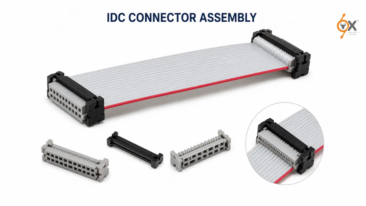
What Is IDC Connector Assembly?
IDC stands for Insulation Displacement Connector.
Instead of stripping wire insulation before crimping, IDC connectors use sharp contact forks that pierce through the insulation and establish direct electrical contact with the conductor underneath.
This makes IDC assembly:
- Faster
- More consistent
- Easier for mass production
- Ideal for flat ribbon cable applications
IDC systems are commonly used in:
- PCB interconnections
- Industrial control systems
- Embedded electronics
- Telecom equipment
- Consumer electronics
- Automation assemblies
When assembled correctly, IDC connectors provide reliable and durable signal connections. But poor assembly technique can reduce long-term reliability significantly.
Tools Required for IDC Connector Assembly
The tools required depend mainly on production volume and connector pitch.
1. Bench Vise for Prototype & Low-Volume Work
For small production runs or prototype assemblies, a bench vise is commonly used.
The connector is placed between flat jaws and compressed evenly until the connector halves fully close.
Important Tip
Pressure must be distributed evenly across the full connector width.
Avoid using:
- Pointed pliers
- Adjustable slip-joint pliers
- Uneven jaw tools
These can crack the housing or create uneven terminations where some contacts do not seat properly.
If the vise jaws are narrow, flat support blocks can help distribute force evenly.
2. IDC Hand Press for Production Use
For medium-scale production, a dedicated IDC press tool is the better solution.
These tools provide:
- Consistent pressing force
- Faster assembly
- Better repeatability
- Reduced operator error
Most production facilities prefer dedicated hand presses because they improve consistency across large batches.
For smaller pitch connectors like 1.27mm and 2.00mm, the die must match the connector series exactly.
Using the wrong die damages the connector housing and affects contact seating quality.
3. Pneumatic IDC Press Machines
For high-volume manufacturing, pneumatic or semi-automatic IDC machines offer the highest efficiency.
Advantages include:
- High throughput
- Controlled press force
- Reduced labour dependency
- Better process validation
Many automated systems also record press force data for quality control documentation.
Step-by-Step IDC Crimping Process
The actual IDC crimping process is straightforward – but the sequence matters.
Skipping steps or rushing assembly often creates failures later in the field.
Step 1 – Cut the Ribbon Cable Properly
Always cut the ribbon cable perfectly straight at 90 degrees.
Uneven or angled cuts create inconsistent conductor entry into the IDC contacts.
This can lead to:
- Partial contact penetration
- Weak electrical connections
- Inconsistent crimp quality
Use a sharp cutter or dedicated ribbon cable cutting tool for clean edges.
Step 2 – Identify Pin 1 Correctly
This is the most critical step in the entire assembly process.
On standard grey ribbon cable:
- The red stripe indicates Pin 1
On IDC connectors:
- Pin 1 is marked with a triangle, arrow, or molded indicator
Before placing the cable into the connector, confirm that the red stripe aligns with the Pin 1 side of the connector.
Why This Matters
Reversed polarity is one of the most common ribbon cable assembly mistakes.
And once the connector is fully crimped, this error is often impossible to detect visually.
Step 3 – Position the Cable Correctly
Open the IDC connector and place the cable flat into the lower housing.
Make sure:
- The cable sits straight
- The edge is fully flush
- No twisting is present
- The cable aligns naturally with the guide grooves
Never force the cable into position at an angle.
Angled insertion can cause adjacent conductors to contact incorrect pins.
Step 4 – Hand-Close the Connector
Before pressing, gently close the top cover by hand.
This temporarily locks the cable in place and allows one final alignment check.
At this stage verify:
- Pin 1 orientation
- Straight cable positioning
- No twisting
- Flush cable seating
This small verification step prevents many assembly errors later.
Step 5 – Press to Full Closure
Now place the connector into the press tool and apply force evenly until the housing fully snaps closed.
A correct termination should show:
- No visible side gaps
- Fully seated cover
- Uniform closure around the connector
If one side remains partially open, the pressing force was uneven.
Avoid re-pressing the same connector multiple times because damaged IDC contacts may no longer terminate correctly.
In most cases, re-termination on a fresh cable section is safer.
Step 6 – Attach the Strain Relief
Many IDC connectors include a strain relief clip.
This step is often ignored during assembly – but it is extremely important for long-term reliability.
The strain relief reduces stress transfer from cable movement directly onto the IDC contacts.
Without strain relief:
- Cable pulling force reaches the contacts
- Contact pressure gradually weakens
- Field failures become more likely
For equipment exposed to vibration or regular servicing, strain relief is essential.
Step 7 – Final Verification
Before installation, perform a basic inspection.
Check for:
- Proper connector closure
- Straight cable alignment
- Correct pin orientation
- Secure cable retention
- No visible housing damage
If possible, continuity testing should also be performed before installation into the final equipment.
Mating the IDC Connector to the PCB Header
When connecting the IDC socket to a PCB box header, align the polarization key properly before insertion.
Never force the connector into place.
If insertion feels difficult:
- Inspect for bent header pins
- Check alignment again
- Verify connector orientation
For ejector headers, secure the locking levers fully after insertion.
Partial seating can create intermittent signal failures that are difficult to diagnose later.
Common Ribbon Cable Assembly Mistakes
Even experienced production teams occasionally encounter assembly issues.
Here are the most common failures seen during FRC cable termination.
1. Reversed Pin 1 Orientation
This is by far the most common assembly error.
In non-polarized systems, the cable may physically fit even when reversed.
Depending on the circuit, the result may be:
- Immediate failure
- Intermittent malfunction
- Damaged PCB components
The solution is simple:
Never skip the Pin 1 verification step.
2. Uneven Press Force
Improper tools or uneven pressing leave some contacts partially seated.
The connector may initially pass continuity testing but fail later during vibration or thermal cycling.
This is why proper IDC tooling matters.
3. Angled Cable Entry
If the cable enters the connector at an angle, adjacent conductors may contact incorrect pins.
This creates cross-connections that are difficult to detect visually.
Always ensure the cable sits straight before pressing.
4. Skipping Strain Relief
Skipping strain relief may save a few seconds during assembly but creates reliability problems later.
In moving or vibration-prone equipment, strain relief significantly improves connector lifespan.
5. Wrong Cable Pitch or AWG
Using incorrect ribbon cable specifications causes unreliable contact penetration.
Examples include:
- 00mm cable with 2.54mm connector
- Incorrect AWG cable size
- Non-compatible IDC cable types
Always verify cable pitch and AWG against the connector datasheet before assembly.
Reliable IDC & FRC Connectivity Solutions in India
OX Connections supplies high-quality IDC connectors, FRC connectors, and flat ribbon cables across multiple pitch configurations including 1.27mm, 2.00mm, and 2.54mm.
With fast dispatch across India and a wide inventory of electronics interconnect products, OX Connections supports OEMs, automation manufacturers, panel builders, and electronics distributors with dependable supply and industry-standard quality.
Final Thoughts
A reliable IDC connector assembly depends less on complexity and more on process discipline.
Simple checks like:
- Correct Pin 1 orientation
- Proper cable alignment
- Even pressing force
- Using correct cable pitch
- Installing strain relief
can prevent the majority of field failures seen in ribbon cable assemblies.
Whether you’re handling prototype builds or large-scale production, following the correct IDC crimping process ensures better reliability, fewer service issues, and more consistent assembly quality.