
IDC connectors and FRC connectors are among the most widely used interconnect systems in electronics manufacturing. From industrial control panels and embedded systems to telecom equipment and consumer electronics, these connectors provide a fast, reliable, and cost-effective solution for multi-conductor signal routing.
Despite their widespread use, IDC connector systems are often selected based on familiarity rather than proper specification. An incorrect pitch, mismatched flat ribbon cable, or unsuitable connector type can lead to assembly rework, intermittent signal issues, and long-term reliability failures.
This guide explains how IDC termination works, how to select the correct pitch and connector type, where flat ribbon cable assemblies are used, and what engineers and procurement teams should verify before sourcing IDC FRC connector India solutions.
What Do IDC and FRC Mean?
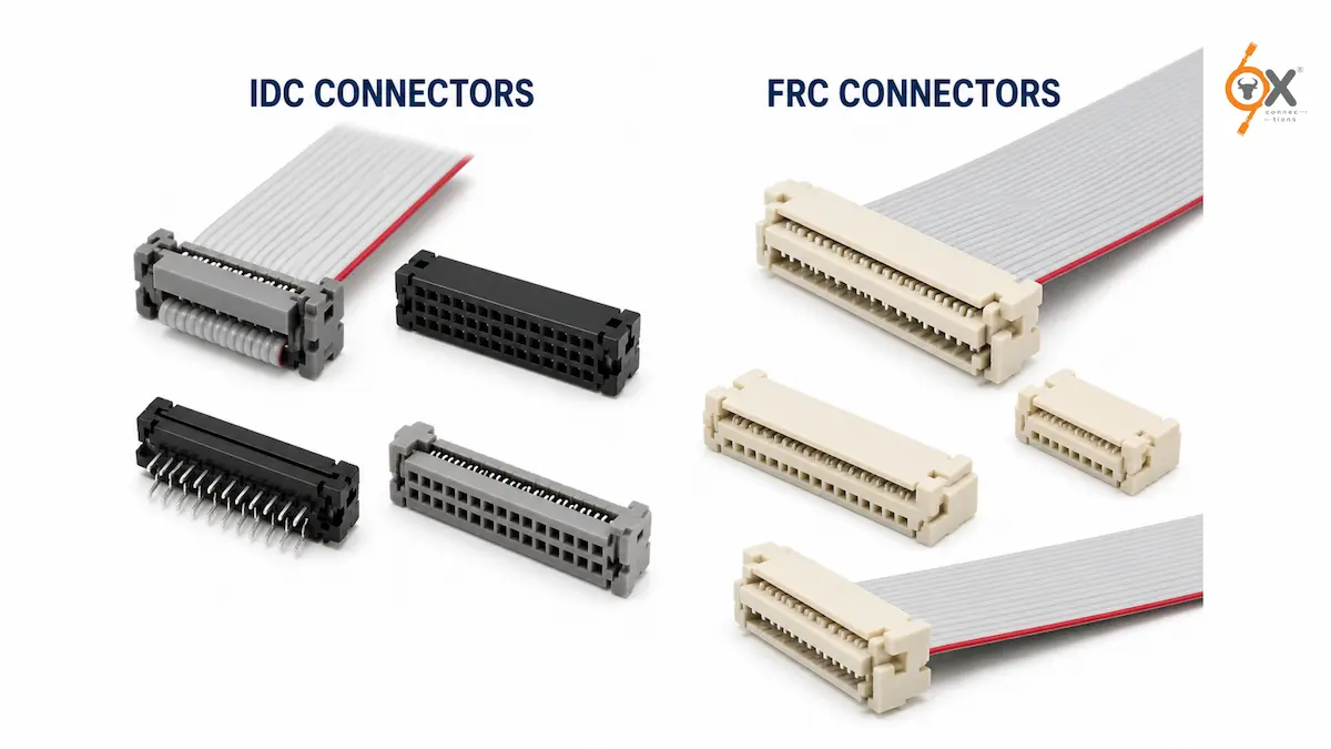
Although the terms are frequently used together, IDC and FRC refer to different parts of the same interconnect system.
- IDC stands for Insulation Displacement Contact
- FRC stands for Flat Ribbon Cable
In practical usage across the Indian electronics industry, the terms are often used interchangeably to describe the complete assembly – a flat ribbon cable terminated using IDC connectors.
Globally, IDC is the more technically accurate term because it refers to the termination mechanism itself.
The original IDC connector systems were introduced by TE Connectivity (formerly AMP), and many manufacturers today produce compatible TE-equivalent connector series used across industrial and electronics applications worldwide.
When engineers in India refer to an “FRC connector,” they are usually describing:
- An IDC female socket
- Mated with a flat ribbon cable
- Designed to connect with a PCB box header
How IDC Termination Works
The defining advantage of an IDC connector is that it terminates wires without stripping insulation, soldering, or manual crimping.
Inside the connector housing are sharpened fork-shaped metal contacts. During assembly, the flat ribbon cable is pressed into the connector using:
- An IDC press tool
- Arbor press
- Bench vise
- Pneumatic assembly press
As pressure is applied, the contact blades cut through the PVC insulation and establish direct metal-to-metal contact with the copper conductor beneath.
The contact beams maintain continuous spring pressure on the conductor, creating a gas-tight electrical connection that resists oxidation and maintains long-term signal integrity.
Why IDC Connectors Are Popular in Production
One of the biggest advantages of IDC termination is simultaneous multi-conductor assembly.
A 40-pin flat ribbon cable assembly that would otherwise require:
- 40 solder joints
- or 40 separate crimp operations
can instead be terminated in a single IDC press cycle.
This provides major manufacturing advantages:
- Faster assembly
- Lower labour cost
- Consistent contact quality
- Reduced wiring errors
- Improved production throughput
For high-volume electronics manufacturing, IDC connectors significantly reduce assembly complexity.
Understanding IDC Connector Pitches
Pitch refers to the centre-to-centre spacing between conductors or connector contacts.
Three pitch standards dominate the IDC connector market today:
- 54mm
- 0mm
- 27mm
Selecting the correct pitch is critical because the connector, cable, and PCB header must all match properly.
2.54mm IDC Connector – The Industry Standard
The 2.54mm IDC connector (0.1 inch pitch) is the original and most widely used IDC standard globally.
It is commonly found in:
- Industrial control systems
- Printers and scanners
- PLC interfaces
- HVAC systems
- Consumer electronics
- Audio/video equipment
- Legacy computer hardware
If an older design or industrial assembly does not explicitly specify pitch, the 2.54mm IDC connector is usually the default standard.
Its larger spacing also makes it easier for manual assembly and field servicing.
2.0mm IDC Connector Applications
The 2.0mm pitch standard emerged as electronics became more compact.
It is widely used in:
- Embedded systems
- ARM and AVR development boards
- ISP programming interfaces
- JTAG connections
- Compact industrial electronics
Compared to 2.54mm, the 2.0mm system saves PCB space while still remaining practical for manual handling and assembly.
1.27mm IDC Connector Applications
The 1.27mm pitch standard (0.05 inch) is designed for high-density electronics.
Applications include:
- GPIO interfaces
- JTAG debugger connections
- Telecom systems
- Compact automation equipment
- High pin-count signal routing
Because the conductor spacing is half that of 2.54mm systems, 1.27mm IDC connectors allow significantly higher signal density in compact PCB layouts.
This pitch is commonly used in modern embedded electronics where board space is limited.
Important Pitch Matching Rule
A critical rule applies across all IDC systems:
The connector pitch, flat ribbon cable pitch, and PCB header pitch must all be compatible.
Incorrect pitch selection results in:
- Improper mating
- Contact misalignment
- Assembly failure
- Intermittent electrical connection
Pitch mismatches are one of the most common specification errors during procurement and cable assembly.
Types of IDC Connectors
A complete IDC connector system includes both cable-side and PCB-side components.
Understanding the purpose of each connector type helps avoid design and sourcing mistakes.
IDC Female Socket with Strain Relief
The IDC female socket is the primary cable-side connector.
It terminates directly onto the flat ribbon cable and mates with the PCB box header.
Most versions include strain relief wings that clamp the cable body behind the contact zone, reducing stress on the termination points.
These connectors are widely used for:
- Ribbon cable assemblies
- Internal equipment wiring
- Multi-pin signal interfaces
Ejector Header Connectors
Ejector headers include side lever arms that help remove the cable assembly from the mating header.
These are useful when connectors are frequently disconnected during:
- Maintenance
- Field servicing
- Reconfiguration
- Equipment testing
The ejector mechanism reduces stress on the PCB during connector removal.
Straight and Right-Angle Box Headers
PCB box headers are the standard mating components for IDC connectors.
These shrouded headers include polarization features that prevent reverse insertion of the flat ribbon cable connector.
Straight Box Headers
Straight headers allow the cable to exit perpendicular to the PCB.
Right-Angle Box Headers
Right-angle headers route the cable parallel to the PCB surface, helping reduce enclosure height requirements.
Transition Connectors
Transition connectors – sometimes called board-in connectors – allow the flat ribbon cable to terminate directly onto the PCB connector without a detachable socket assembly.
These are typically used in permanent internal wiring applications where field disconnection is unnecessary.
Understanding Flat Ribbon Cable Specifications
The standard flat ribbon cable used with IDC connectors typically includes:
- 28AWG stranded conductors
- PVC insulation
- 300V rating
- 105°C temperature rating
Grey is the standard cable colour, while a red stripe identifies the pin-1 side for proper orientation.
Core counts commonly range from:
- 6 core
- 10 core
- 14 core
- 20 core
- 26 core
- 40 core
- 64 core
depending on the signal requirements of the application.
Current Capacity of Flat Ribbon Cable
Flat ribbon cable used in IDC systems is designed primarily for signal transmission, not high-current power delivery.
Typical current ratings for 28AWG ribbon cable range from:
- 1A to 2A per conductor
depending on:
- Ambient temperature
- Cable length
- Ventilation conditions
For higher-current applications, discrete wire crimp assemblies are usually more appropriate.
Where IDC FRC Connectors Are Used
IDC connectors and FRC connectors are used across a huge range of industries because they combine compact routing with fast assembly.
Consumer Electronics
Common in:
- Printers
- LCD displays
- Audio equipment
- DVD players
- Monitors
- Scanners
Industrial Automation
Widely used in:
- PLC wiring
- CNC machines
- Sensor interfaces
- Control panels
- Signal routing systems
Embedded Development
Common for:
- GPIO headers
- JTAG interfaces
- ISP programming cables
- Development boards
Telecom and Test Equipment
Used for organized high pin-count signal routing inside rack-mounted systems and communication hardware.
What to Verify Before Ordering IDC Connectors
Before placing an order for IDC connectors or flat ribbon cable assemblies, engineers and procurement teams should verify four critical parameters.
1. Pitch Compatibility
Ensure the connector, flat ribbon cable, and PCB header all use compatible pitch standards.
2. Pin Count
Confirm sufficient conductors for:
- Signal lines
- Ground connections
- Power rails
- Future expansion if required
3. Mounting Style
Choose between:
- Straight headers
- Right-angle headers
- Ejector types
- Transition connectors
based on enclosure space and cable routing requirements.
4. Contact Plating
- Tin plating is suitable for standard applications
- Gold flash plating is preferred for higher mating cycles and improved reliability
IDC FRC Connector Solutions from OX Connections
OX Connections supplies high-quality TE-equivalent IDC connectors and FRC connectors across India for industrial and electronics manufacturing applications.
Our range includes:
- 27mm IDC connectors
- 0mm IDC connectors
- 54mm IDC connectors
- Female IDC sockets with strain relief
- Ejector headers
- Straight box headers
- Right-angle box headers
- Transition connectors
- Grey flat ribbon cable
- 6 to 64 pin configurations
With ready stock availability, fast dispatch, and reliable product quality, OXConnections supports OEMs, distributors, and electronics manufacturers across industrial automation, consumer electronics, embedded systems, renewable energy, and control panel manufacturing.
Whether you require standard IDC connector assemblies or custom flat ribbon cable solutions, OX Connections delivers dependable interconnect products built for production environments.
FAQs
What is an IDC connector?
An IDC connector is a connector that uses insulation displacement technology to terminate wires without stripping insulation.
What is the difference between IDC and FRC connectors?
IDC refers to the termination method, while FRC refers to the flat ribbon cable used in the assembly. In practice, both terms are commonly used together.
What is a 2.54mm IDC connector used for?
A 2.54mm IDC connector is widely used in industrial electronics, PLC systems, computer hardware, and general-purpose signal routing applications.
Are IDC connectors reusable?
IDC connectors can typically be mated and unmated multiple times, but the cable termination itself is generally considered permanent once pressed.